
Hydraulic Shore Spacing Guide
Hydraulic shore spacing is determined by the complete protective-system design, not by a single universal distance between shores.
Soil classification, excavation depth, surcharge loads, sheeting requirements, trench length, cylinder placement, and the manufacturer's current tabulated data all affect the required system layout.
Why Hydraulic Shore Spacing Matters
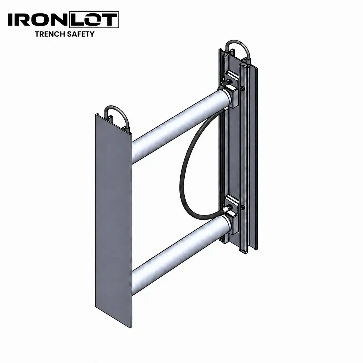
Vertical hydraulic shores work together as a system. Their spacing determines where trench-wall support is provided along the excavation and vertically through the protected depth.
Placing shores farther apart than the applicable tabulated data permits can leave the protective system outside the manufacturer's allowable configuration.
For that reason, spacing should be established by the project Competent Person using the manufacturer's current tabulated data and actual excavation conditions.
There is no single hydraulic shore spacing number that applies to every trench.
Horizontal vs. Vertical Shore Spacing
Hydraulic-shoring layouts involve two different spacing measurements. They should not be confused with one another.
Along the Length of the Trench
Horizontal spacing is the distance from one hydraulic shore location to the next as the system progresses along the excavation.
Allowable horizontal spacing can change with soil classification, excavation depth, surcharge loads, sheeting conditions, and other factors.
Between Cylinder Levels
Vertical spacing refers to the distance between hydraulic cylinders or vertical support increments within the shore configuration.
The current tabulated data supplied with the vertical hydraulic shores sold by Iron Lot limits maximum vertical cylinder spacing to 4 feet.
What Determines Horizontal Shore Spacing?
Horizontal shore spacing should be determined from the applicable tabulated data rather than from a general rule of thumb.
Several excavation conditions can affect the allowable distance between adjacent shores.
Soil Classification and Excavation Depth
Soil classification and excavation depth are major inputs when determining allowable horizontal spacing.
As soil conditions become less stable or excavation conditions become more demanding, the applicable tabulated data may require shores to be positioned more closely together.
The soil should be classified by the project Competent Person before the hydraulic shores are installed. If soil conditions later change, the system may need to be reevaluated and the spacing adjusted.
How Is Vertical Spacing Determined?
Vertical spacing controls the relationship between hydraulic-cylinder locations through the depth of the excavation.
In the current manufacturer tabulated data supplied with the vertical shores sold by Iron Lot, maximum vertical cylinder spacing is 4 feet. The required cylinder locations also depend on the excavation depth and the shore configuration being used.
The locations of the top and bottom cylinders matter as well. A rail length should therefore not be treated as a standalone excavation-depth rating.
The 4-foot vertical spacing limitation does not mean shores should automatically be placed 4 feet apart horizontally along the trench.
How Does Trench Length Affect Shore Quantity?
The current tabulated data also establishes minimum protective-system layouts for short excavations based on the allowable horizontal spacing.
Minimum Two Shores
For a trench whose length is equal to or less than two times the allowable horizontal shore spacing, the tabulated layout requires a minimum of two shores installed in accordance with the spacing requirements.
Minimum Three Shores
For a trench whose length is greater than two times the allowable horizontal spacing, the tabulated layout requires a minimum of three shores set at the required spacing.
The two- and three-shore requirements above describe protective-system layout requirements in the applicable tabulated data. They are not minimum purchase quantities or Iron Lot sales requirements.
How Do Surcharge Loads Affect Spacing?
Loads near the trench can increase the pressure imposed on the excavation walls and therefore affect allowable hydraulic-shore spacing.
The current tabulated data supplied with these shores includes specific assumptions for nearby equipment and spoil-pile loading. Conditions outside those assumptions must be evaluated by the Competent Person, and shore spacing may need to be reduced.
Common surcharge considerations include excavators, loaders, trucks, spoil piles, structures, outriggers, traffic, and other loads close to the excavation.
How Does Sheeting Affect the Layout?
Vertical hydraulic shores do not create continuous wall coverage. Portions of the soil remain exposed between adjacent shore locations.
Where sloughing or raveling is likely, allowable sheeting may be required. If material continues to slough or ravel between sheeting, the applicable tabulated data may require spacing to be decreased until the condition is controlled.
Sheeting is therefore part of the complete system layout and should be considered when determining shore spacing, not added independently without reviewing the tabulated requirements.
Spacing May Need to Change During the Job
A spacing layout established at the beginning of an excavation should not be assumed to remain appropriate if the jobsite conditions change.
The Competent Person should monitor the shored excavation for conditions that can affect the system, including water seepage, soil movement, surface cracking, sloughing, raveling, surcharge changes, and damaged or loose shores.
If conditions change, the soil classification, shoring configuration, sheeting, or spacing may need to be reevaluated before work continues.
A Practical Hydraulic Shore Layout Process
A hydraulic-shoring layout can be approached as a sequence rather than by starting with a preferred shore spacing.
Determine the soil classification immediately before installing the protective system.
Confirm trench depth, width, length, and actual field conditions.
Account for equipment, spoil piles, traffic, structures, and other nearby loading.
Evaluate whether sloughing or raveling requires allowable sheeting.
Determine allowable horizontal and vertical spacing for the actual conditions.
Reevaluate the layout when soil, water, surcharge, or other jobsite conditions change.
Spacing Comes From the Tabulated Data
Do not choose hydraulic shore spacing from a general rule of thumb or from trench length alone. Soil classification, excavation depth, vertical cylinder placement, surcharge loads, sheeting, changing conditions, manufacturer tabulated data, and Competent Person review all affect the complete protective-system layout.
Need Hydraulic Shoring for an Upcoming Project?
Iron Lot supplies vertical hydraulic shores and related hydraulic-shoring equipment for underground utility, municipal, public works, and excavation projects. Contact us for current pricing, availability, and freight coordination.